
In the previous chapter, we made operators that can add and subtract binary devices. To save the results, we made registers and more space for memory again. Now it’s time to output the results of the calculations to the user.
Seven-segment digital display
The simplest output device can be a row of redstone lights that display binary numbers one by one. In this example, we use a two-digit digital tube to represent the data in hexadecimal.
Why is it hexadecimal often used?
The increase in the number of bits in decimal is not synchronized with binary. For example, 15 and 16 are both two digits in decimal, but in binary the former is four digits 1111 and the latter is five digits 1 0000. 100 has one more digit than 99 in decimal, but in binary they are represented by 110 0100 and 110 0011, respectively, with the same number of digits.
When converting a decimal number to binary, you have to keep dividing the whole number, no matter how big the number is.
In hexadecimal, numbers exceeding 9 will be replaced by the six letters abcdef. More than 16 in hexadecimal goes into 1, which is more than 2^4 into one, corresponding to four bits in binary. When doing the binary conversion, you only need to write out the binary numbers corresponding to each bit before putting them together. Take F5 as an example, F(16)=1111,5=0101, so F5 in binary is 1111 0101. This can be done no matter how long the data to be converted is.
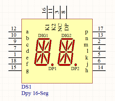
The seven-segment digital tube has a total of seven line segments that can turn on and off. Different combinations of line segments are used to represent different numbers. Between the digital tube and the binary input lines, a digital tube decoder curcuit needs to be added to convert the binary numbers into the light-up and light-down combinations of the lines. In Minecraft, a relatively efficient decoder structure is as follows.

In the design shown in the figure, seven horizontal lines connect each of the seven line segments of the digital tube for display. Vertically, there are 16 control lines responsible for the ten digits and six letters. Each longitudinal line segment is coded with a number with or without a red stone torch. By extinguishing the red stone on a specific control line, the specified number is displayed.
Using a multiplexer to control sixteen lines, and then using the four binary digits to be converted as input, you can light up the specified control line based on the input.
Multiplexers can be made using the code-gate structure mentioned in the previous blog. When response time is not important, a time-delayed structure can also be used to reduce the size. When two decoders with multiplexers are placed side by side, the module looks like this:
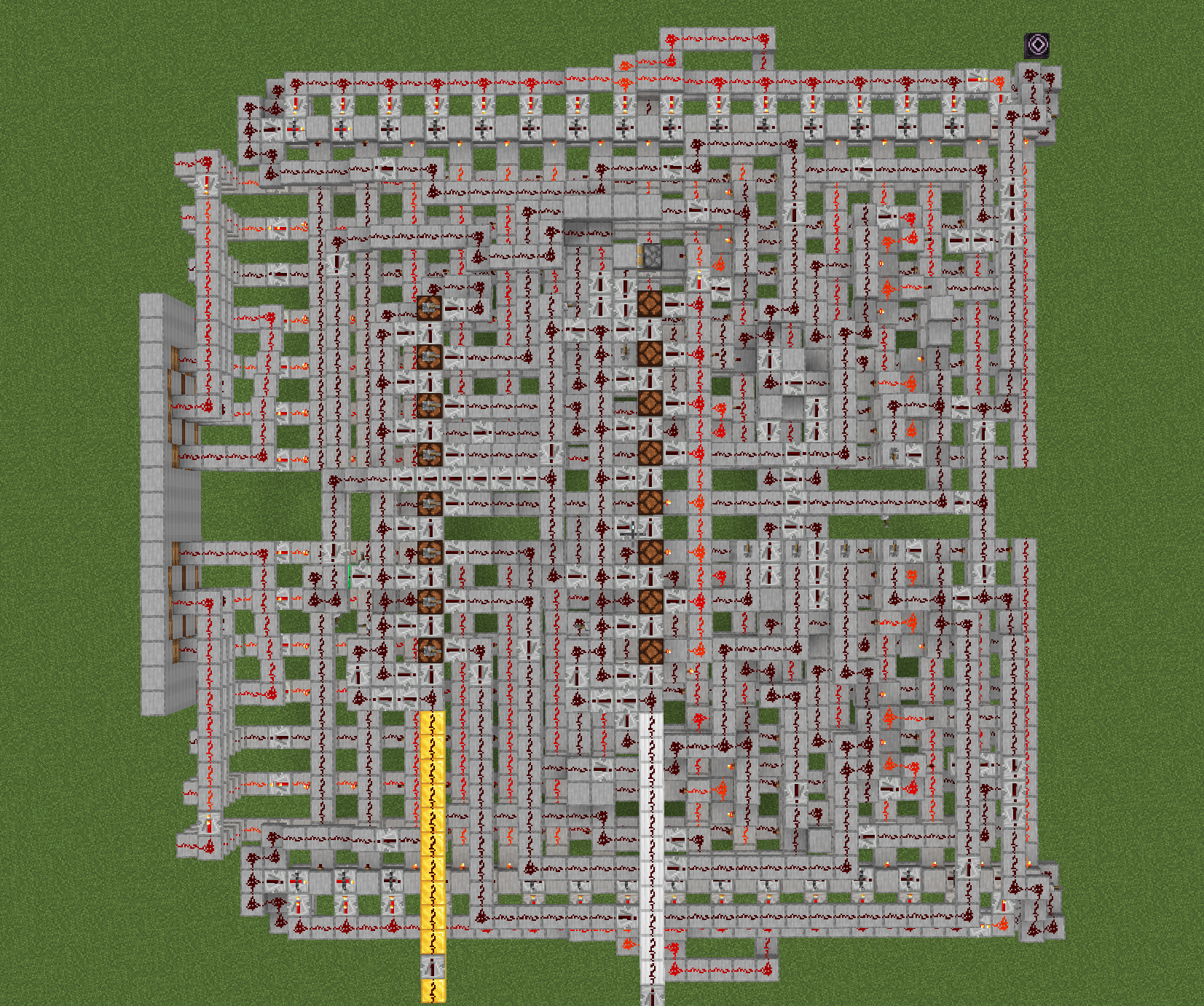
The gold and white lines are the input lines for the data and part codes. We’ll see how this part works later.
Serial bus
There are two ways to transfer eight bits of binary data. The simplest method is to transfer in parallel, just draw the signal lines for each bit directly through. Parallel transmission is convenient when connecting within parts, for example by connecting one row of half adders to another row of half adders. Pulling so many wires may not be a good idea when the distance is long or when there are more parts to connect. You may have seen super complicated Redstone computers elsewhere – they tend to have a large number of transmission cables placed side by side and look very large and complex.
One effective way to reduce the number of cables is serial communication. Unlike parallel communication, which transmits eight digits at a time over eight cables, serial communication transmits eight signals over the same wire in eight moments. As shown in the figure.
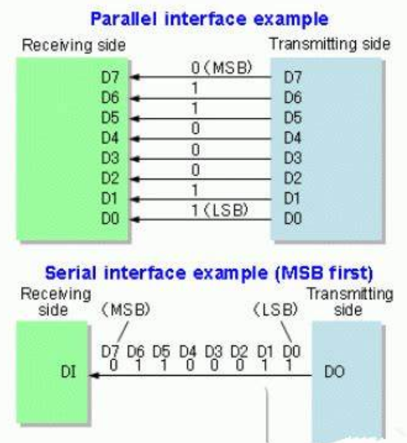
In serial communication, the sender and receiver transmit data bit by bit at an agreed rate. Some serial communication uses a second clock line to ensure synchronization. Fortunately, Minecraft has a fixed “redstone tick” time. 1 redstone tick is equivalent to the delay time in the default state of a redstone repeater, which is the smallest unit of time in most redstone systems. In order to make the transfer as fast as possible, we might as well set the unit time for serial communication to one tick.
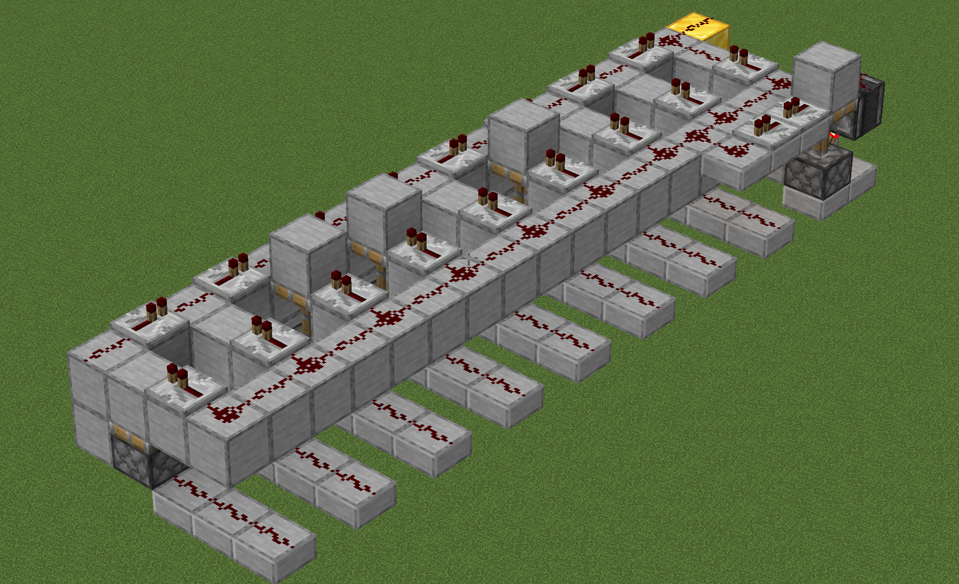
The serial transmitter accepts a parallel input and sends it out as a serial signal. It is structured as shown in the diagram. A raised square will allow a signal to pass on that bit, and when lowered, no signal will pass.
Remember the “locking” feature of the Redstone repeater mentioned in the register unit? We’ll use this feature to make a Redstone receiver. The receiver detects the “start” pulse of the serial model header and starts the timing, then locks and saves the signal when it passes the repeater string exactly.

Bus design
When only two devices need to communicate, it is easy to connect their inputs and outputs to each other. If there are many parts, they need to be connected to each other using a bus.
The bus is the common communication trunk for transferring information between various functional components of the computer. All components are connected to the bus, and data on the bus will be received by all components. Buses are one of the few structures that are more difficult to make in Minecraft than in reality. redstone repeaters used for long distance transmission in Minecraft are directional, so the data on the line can only flow in one direction. In order to send the whole line at any point to receive the characteristics like the real bus, the unidirectional bus needs to be made into a ring.
There are five buses in our design. The data bus is connected by all devices to all devices and is responsible for transferring the data to be manipulated. The data address bus indicates the recipient of the data on the data bus. The operation completion line is responsible for returning a pulse to the controller when the operation is complete, instructing the controller to continue with the next step. The remaining two buses are reserved for use by the controller in the next section.
For all components with receviers, they have the follow workflow:
Receives data broadcast from the data bus; checks the address of the destination device subsequently sent on the address bus; if the destination address does not match its own id, the data will be discarded and the data bus receiver reset. If the destination address is its own id, the data on the receiver will be fed for internal processing. After the processing is complete (e.g. the line feed adder has produced a result), a pulse will be given to the operation return line. If new data is generated (e.g. the result of an addition), the serial transmitter will broadcast the new data on the data bus.
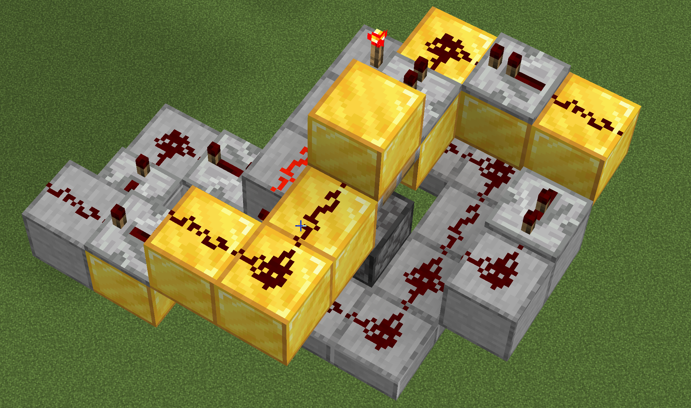
Connecting two serial bus receivers together will complete the data reception and check the address. The diagram below. Note that the silver line is the input for the data destination address and the gold is the input for the data.

All devices have to receive the data on the bus and inform the controller when the execution is complete. Therefore they all need the receivers in the figure. You can save and name the receivers with structured squares and just place them when you use them. In the next section, we will use the controller to control them uniformly and execute the program.
https://ltyxh.com/en/redstone-cpu-4/