
Now we have learned what binary is and the basic operations of Boolean logic variables. For example, how to perform logical operations on two boolean values: AND , OR and NOT. Be sure to become proficient at building these logic gates in Minecraft, because we will be using them a lot from this chapter on.
These logic gates are like Lego bricks, and with them we can implement more complex functions. For example, adding two numbers together.
Ripple-Carry Adder
There are 4 outcomes to add two single digit binary.
| A | B | Result |
| 0 | 0 | 00 |
| 0 | 1 | 01 |
| 1 | 0 | 01 |
| 1 | 1 | 10 |
The result is a two-bit binary number, which means that we need two outputs for each bit.The output of the digit is in fact equivalent to doing an XOR operation on two numbers: if the two numbers are the same, e.g. both are 0 or both are 1, the result of the respective digit is 0. Only when the two numbers are different, where one is 1 and the other is 0, the result is 0.
The output of the digit is in fact equivalent to doing an XOR operation on two numbers: if the two numbers are the same, e.g. both are 0 or both are 1, the result of the digit is 0. Only if the two numbers are different, one is 1 and the other is 0, the result of the digit is 1. By putting an iso-or gate after the input, the result of the digit is obtained.
Observe the tens place of the result (i.e., the incoming digit). Only when both numbers are 1, the sum result is 10. This is the logic of how OR gates work. By putting a OR gate after the input, we get the tens place of the result. Now put the with-gate and the XOR gate together, and we have a semi-adder that can compute one-digit binary addition.
A calculator that can only calculate one digit is probably not very useful. To calculate more than one digit we need a full adder that can handle rounding. Unlike a half adder, a full adder, after adding two outputs, will add the result and the rounding up again. The truth table is as follows.
| input A | input B | carry input | carry output | output |
| 0 | 0 | 0 | 0 | 0 |
| 0 | 0 | 1 | 0 | 1 |
| 0 | 1 | 0 | 0 | 1 |
| 0 | 1 | 1 | 1 | 0 |
| 1 | 0 | 0 | 0 | 1 |
| 1 | 0 | 1 | 1 | 0 |
| 1 | 1 | 0 | 1 | 0 |
| 1 | 1 | 1 | 1 | 1 |
A full adder is actually two half-adders connected together. The first half adder is responsible for adding the first two inputs, the second half adder is responsible for adding the result and the incoming bits, and then processing the incoming bits they produce with an or gate. We can build a semi-adder in Minecraft like this.
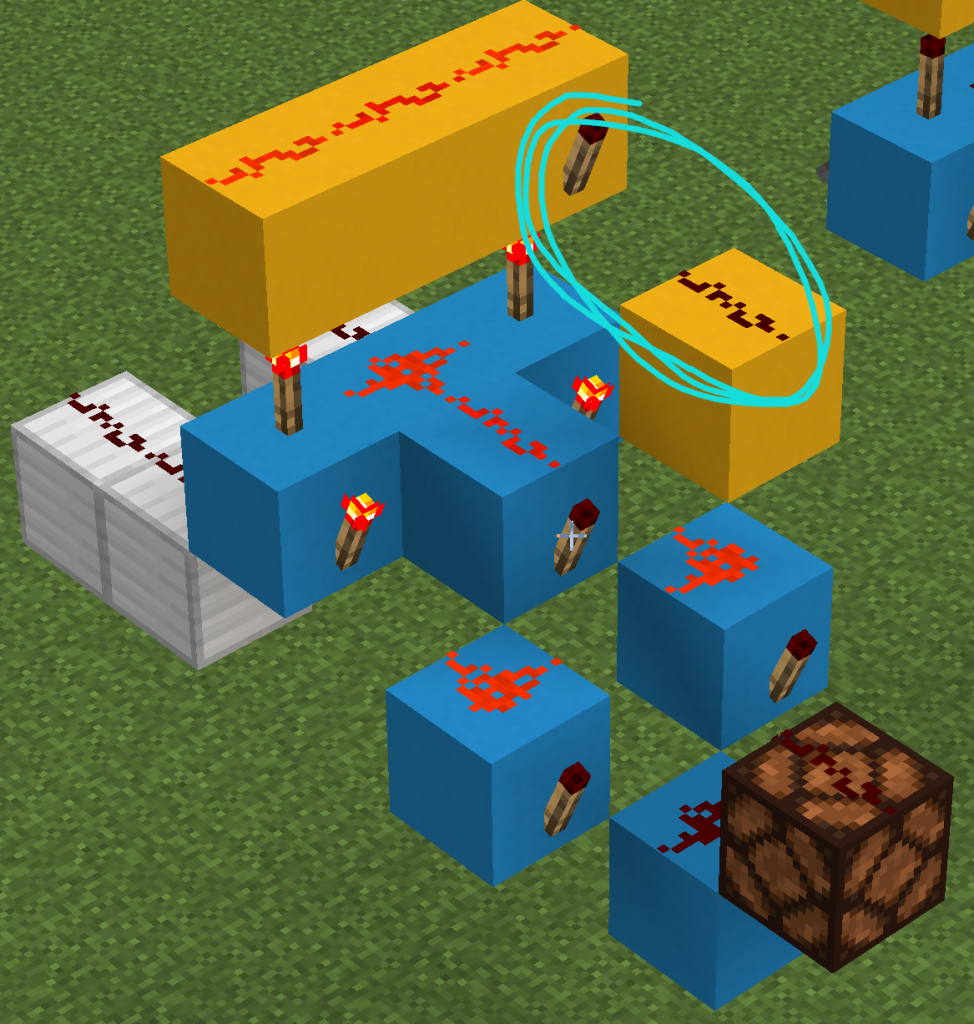
The iron blocks on the left side of the diagram are the two inputs of the half adder, and the blue part is an XOR gate whose signal will be output to the red stone lamp in front. The yellow part is an AND gate that generates a feed, the result of which will be output to the square marked with a cyan pencil in the diagram.
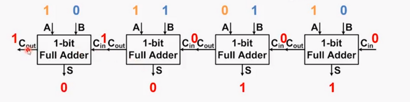
By forming two half adders into a full adder and transferring the result of the rounding of this bit to the next full adder, we are able to calculate multi-bit addition. This type of step-by-step adder is called a Ripple-carry adder.
In minecraft, a ripple-carry adder looks like this:
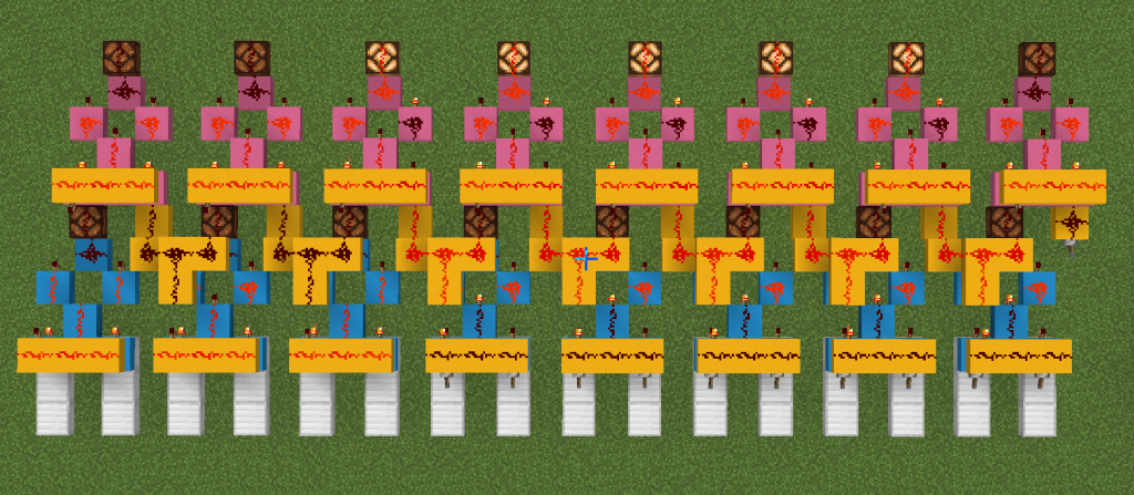
Observe how the eight-bit adder in the diagram implements a left-to-right feed. The first half adder in each full adder from the far right (blue) adds the two inputs and passes them to the second half adder (pink). The second half adder adds the input of the first full adder to the previous bit of the integer (yellow) to get the final result. The feeds generated by the two half adders are summed by the yellow line and passed to the next full adder.
The last full adder produces a feed that is simply discarded because it exceeds eight bits, at which point the full adder will output the wrong result. We call such a situation an overflow.
In the case of overflow, the calculated result is one bit less than the actual result, and the value is 1 0000 0000 less. remember this, it will be used later!
Subtraction and negative numbers
One possible way to calculate subtraction is to build a subtractor like an adder. Write out the rules for calculating each bit and the borrowing rules and then make a full subtractor out of it. But most of the time another method is used: calculating A-B is actually calculating A+(-B), which is the negative of A plus B. We just need to represent B with a negative number.
The representation of a number written out directly in binary is called the Sign-Magnitude, while computers use something called the Two’s complement to represent negative numbers. According to the rules of the complement, the first of the eight signed integers will be used to represent positive and negative. A positive number is 0 and a negative number is 1. The two’s complement of a positive number is itself (i.e., the Sign-Magnitude), and the complement of a negative number is its absolute value of the Sign-Magnitude inverse of the original code bit by bit plus 1.
For example, for -1’s two’s complement, we can first write out the sign magnitude of its absolute value: 0000 0001. inverse bit by bit to get its one’s complement 1111 1110, and add 1 to the inversed result to get its two’s complement code 1111 1111.
Let’s try to do some addition! For example, 2 + (-1). the binary value of 2 is also its two’s complement, which is 0000 0010. the two’s complement of -1 is 1111 1111.
0000 0010 + 1111 1111 = 1 0000 0001. Note that our number has only 8 bits, so any bits beyond that are discarded. The result is that the last eight bits are retained as 0000 0001, which is 1.
2-1=1. That’s correct, but why?
In our way of calculating, since the excess of 8 bits is discarded, 1111 1111 plus one goes back to 0000 0000, just like the clock hand goes back to 1 after 12. The two’s complement is equivalent to adding 1 0000 0000 to all negative numbers – this gives us a positive number for calculation. The 1,0000,0000 that is added is discarded in the calculation due to overflow. It’s as if 8 hours after 7:00 on a clock dial is 7+8=15 and we discard 12, 15-12=3.
Binary multiplication and division also use very smart methods to calculate. If you are interested, you can spend some extra time to learn it.
Register
After performing addition and subtraction calculations, we need a draft paper-like storage space to hold the result of the calculation. A register can hold a number and be read when needed.
As always, we’ll start by learning what happens when there’s only one. a feature of the redstone repeater in Minecraft allows us to conveniently save the current state:
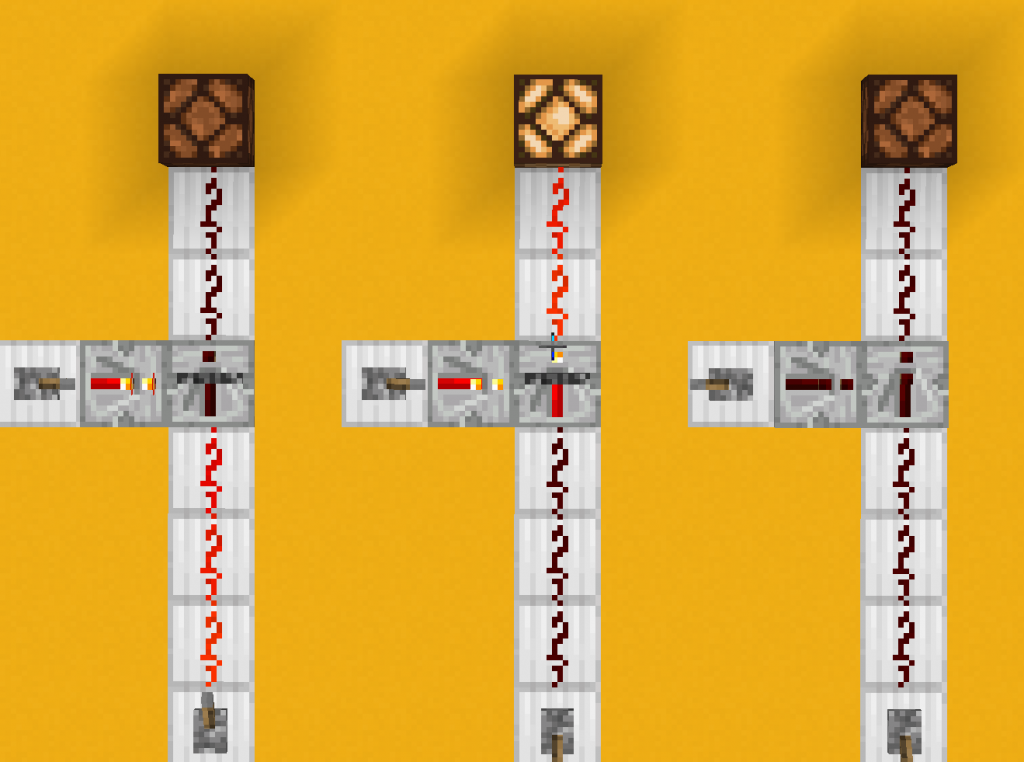
When a Redstone Repeater is charged from the side by another Redstone Repeater, it “locks”. In the locked state, the output signal does not change, no matter how the input signal changes.
Therefore, a binary number can be saved by simply placing a line of repeaters and controlling lock/unlock uniformly with a redstone line.
Memory
For a real computer system, one byte of storage space in a single eight-bit register is obviously not enough. Two registers are not enough either. Microcontrollers that can implement simple functions, such as the Arduino uno, often have thousands of bytes of memory in size. These memory spaces are numbered with memory addresses, and we can access specified locations in memory by memory address.
A memory module consists of a very large number of memory cells. They share input and output ports, and the memory modules select specific memory cells for read and write operations based on their addresses.
Let’s build a 64bit memory. If we just lined up 64 registers together, our memory module would be impractically long. So instead of lining them up, let’s use an 8×8 matrix instead. First we make stackable cells like this.


Such modules can be stacked horizontally and vertically. The yellow horizontal lines are the read and write lines for data. The blue one is a write enable line that switches uniformly from the bottom up. The cells in the matrix are positioned using two lines: the green row selected and the orange column selected. For address row 7, column 2, the memory module will turn on the row select line for row 7 and the column select line for row 2. The size of the memory module is 64, which is a 6-bit wide address. Bits 1-3 of the address represent the columns and bits 4-6 represent the rows.
When both row selection and column selection are active, the memory cell will output the stored data state (high or low) on the data output line. If a pulse is given on the write enable at this time, the cell will unlock and relock the redstone repeater, updating the stored value to the value on the data input line.
By stacking eight of these modules vertically like this, we have a large module of memory with a bit width of 8: you can store a byte!
By stacking the vertical “byte towers” 8×8 on a flat surface, we can store 64 bytes. Finally, remember to connect the row selection of each row and the column selection of each column in series, so that we can select several rows and columns.
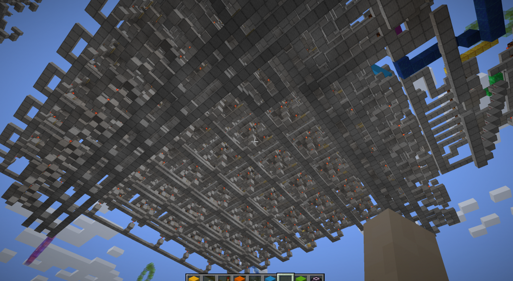
Once completed, such a module looks like this from the bottom, where you can see a horizontal column selection center line.

How to light up the corresponding address line according to the serial number of the binary? Introducing…
Multiplexer
Let’s first consider a relatively simple problem: How do you determine if a binary value is 110?
We can convert this problem to: if given three inputs, how can we determine if the first input is 1, the second input is 1, and the third input is 0?
The following logical expression can be written: Result = (Is A 1?) AND (is B 1?) AND (Is C 0?)
is equivalent to: result = A AND B AND (!C).
This is the principle behind the coded gates commonly found in Minecraft community maps. The output is 1 when and only when the input value is a specific binary number.
Let’s build it out. (The design below has been simplified somewhat and the actual logic principle is equivalent to that mentioned above)

Now we are ready to decide whether to select a line based on the binary number. Next it’s just a matter of making the remaining multiplexers and having them share inputs. The finished product will look like the bottom of the memory in the previous picture.
Now you have a working memory module! To read the value of the specified memory location, we just need to enter the correct address and the value will be output; to rewrite the value of the specified location, you should write the data at the data input and write the address to be modified at the address; finally, give a pulse signal to the write enable line.
In the next chapter, we will learn how to connect components together and transfer data efficiently.
Comments