
The first three chapters of this tutorial describe the components of a computer, the building of memory and ALUs and how to connect them together. In this chapter, we will make a controller that gives instructions and write and run our first program.
Instruction cycle and program counter
A program is a series of instructions arranged in a sequence. Instructions indicate exactly what the CPU needs to do at the current step, such as whether to add two numbers or load data from memory into a register. A program is loaded into the computer’s memory as a series of instructions when the computer is booted.
Computers use program counter(PC) to keep track of where a program has run. The program counter is a register that holds the memory address of the current instruction. Each time the computer is turned on the program counter will reset and point to the first instruction of the program. When an instruction has finished running the program counter will add 1 to its value and point to the next instruction in memory. Manually modifying the program counter value can change the program’s running position. This allows for a jump operation, such as jumping back to the program header after the last instruction is executed and executing the program again. This type of execution is called a loop structure.
There are four main steps in the process of computer execution of instructions.
The computer will repeat these four steps until the program is finished. Let’s demonstrate this with a sample program.
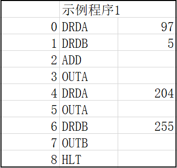
Before we can execute this program, we need to first load the program into memory at the memory address on the left. In our Redstone computer, the program has already been written into memory in advance.
Reset
After power on, the computer sends a reset signal to all components. The serial bus receiver will be ready to receive the signal and the registers will be cleared. The program counter will be reset to point to memory address 0.
Fetch
Our computer contains two memory modules storing instructions and data respectively. At the beginning of each instruction cycle, the program counter sends the saved values to both memory modules via the memory address bus. The controller will send a fetch signal to the memory modules. The memory module receives the signal and connects the output to the decoder. This completes the fetch instruction phase.
Decoder
Each instruction corresponds to a different specific operation. For example, loading data on the current address to register A (DRDA) can be broken down into the following steps: the data memory module broadcasts the current data on the data; the controller sends a control signal on the data address line to specify that the data is received by register A; register A receives the control signal, the target address matches its own id, and updates its own data.
The structure that converts instructions into specific operations and sends control signals sequentially on the bus is called a decoder. First, the instructions are fed to a multiplexer with all decoder units connected. The multiplexer activates the corresponding decoder units according to the different instructions. A single decoder unit contains a series of pre-coded bus transmitters. After receiving the “execution complete” signal from the previous device, the decoder will send the next signal. The structure of the decoder is shown in the following figure.
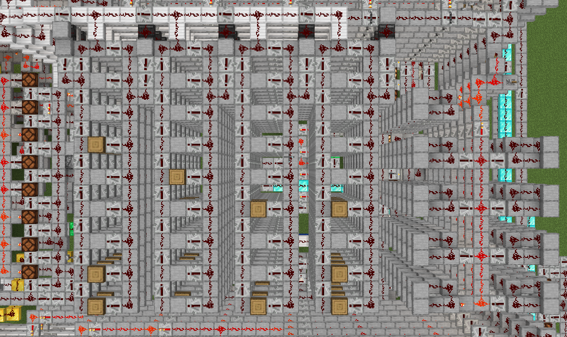
The picture shows the topmost layer of the multilayer decoder. On the far right side of the picture is the eight-bit multiplexer, which has been set to 0001 0000 instruction in the picture. The executor ids to be sent to the control bus are set by the wooden block are 0000 1011,0000 1001,0001 0000 and 0010 0011 from right to left. the necessary data write back will also be done at this stage. After all four transmitters have been sent a program counter pulse will be signaled, representing the end of this instruction and the next finger picking cycle.
Instruction Sets and Turing Machines
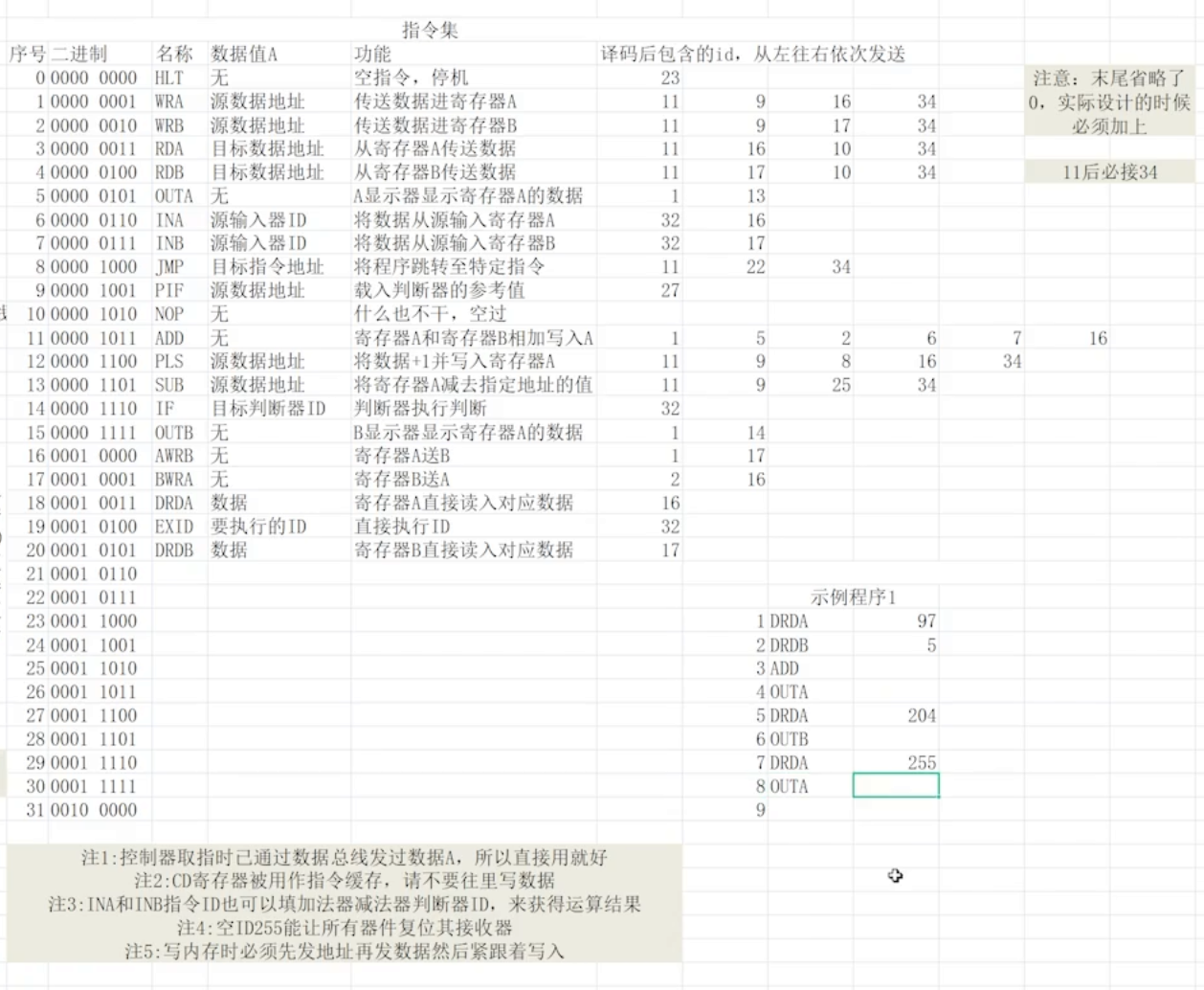
The instruction set is a collection of all instructions that the CPU is designed to run and describes all operations that can be executed. Instructions are divided into two parts: opcodes and operands. The former describes the operation to be executed and the latter is the required extra information.
For example, in the instruction set below, WRA 0001 1001 represents an instruction with operand WRA (transfer data into register A) and operand 0001 1001 represents the address of the data to be transferred in the data memory.
Programs written directly in binary can be difficult to read. Instead of recording the binary directly, we might as well use the name of the instruction instead. This type of programming is known as compilation.
Instruction sets are divided into many types based on characteristics such as length. In our example, the opcode and operand are fixed eight bits long. It is called a sixteen-bit fixed-length instruction set (opcode and operands add up to sixteen bits).
Most computers in real life are Turing machines. The specific definition of a Turing machine is related to the theory of computation. A computer with Turing completeness is able to perform all computational problems and has the following basic operations: a linear memory space is considered as a paper tape that can be used to record data, the computer is able to manipulate the current memory, to modify values (self-incrementing, decreasing, zeroing, etc.), to have control flow operations (making judgments), to perform loops (jumping back to a specific location), etc. to a specific position), etc. The specific instructions include conditional judgments (execute… if… condition is met), and jumps (jump back to the head of the program to continue execution when it reaches this point).
We have implemented the manipulation of data, let’s understand how the control operation is performed.
Jump and Loop
Loop structure is a topic that cannot be avoided in programming. Implementing a loop in a program requires a jump instruction, i.e., a jump to a specified program location before continuing. If you have written languages such as visual basic, you should be familiar with the goto – they do basically the same thing.
Jumping in a program depends on the program counter. The program counter holds the position of the currently executed code, and a jump is made by changing the program counter value to the position to be jumped to. When the value in the program counter is changed, the computer will fetch instructions based on the new value.
A loop without a condition is an infinite loop, and our program will get stuck in it and execute repeatedly until it stops due to an error such as an overflow. To jump out of a loop, we can add a judgment (if statement) to the jump instruction or, alternatively, skip the jump instruction when a specific condition is met.
Common judgments in programming can be implemented in some clever ways. An adder can be used to implement a larger-than-small class of judgments. Adding a number to the opposite of another number (remember how to do that with negative numbers? It is explained in Chapter 2), and if the result is zero, you can be sure that the two numbers are equal; add a number to the negative of another number, and determine whether the result is negative (look at the first place of the complement!) Then you can achieve the operation of comparing value.
The showcase of Redstone computer base on this tutorial is below:
https://www.bilibili.com/video/BV15y4y1t7Eg?p=2