
Filter
Sometimes when mixing or sound processing, we want to remove, reduce or enhance some frequency bands. For example, when you reverse engineering the bass of a song, you can insert a high-cut (low-pass) filter to listen to only the low frequencies band.
These operations are pretty simple in the frequency domain. Just multiplying the signal in the corresponding frequency band by a specified value. If you want to enhance high frequencies, you can double the frequency components of all high frequencies.
The familiar PCM format records the time domain information of audio. So to adjust itsthe frequency, you have to Fourier transform it to the frequency domain and inversely transform it back to the time domain after process. Right?
You certainly can, but it is not recommended.
There are many reasons for this: first of all, the Fourier transform is very computationally intensive, even for the $O(n \log n)$complexity FFT algorithm, it still requires a lot of trigonometric floating-point operations, and after processing the signal in the frequency domain, it has to transform back with about the same number of calculations. This is virtually unacceptable for producers who insert dozens of software effectors.
Secondly, considering that the spectrum of the audio is dynamic over time, we have to apply STFT algorithms that will split the audio first. During each split there will be an slight error – resulting in the reduction of audio quality.
How can we edit the frequency domain without performing any Fourier transforms?
Let’s find out the answer from the analog circuits.
RC filter circuit
In an analog circuit, the audio waveform is represented by the change in voltage. A sine wave audio signal is reflected in a circuit as a sinusoidal alternating voltage, which is familiarly known as AC.
In a circuit, inductors and capacitors act like reservoirs by storing energy. An inductor stores electrical energy as magnetic energy and produces a reverse voltage when the current changes, preventing sudden changes in current. A capacitor, on the other hand, stores charge on both poles, which flows in and out when the voltage changes, slowing the voltage change. These are called electrical impedance. The impedance value is a complex number. For a sinusoidal alternating current of fixed frequency, the real part of the impedance is the ratio of current to voltage (same as Ohm’s theorem), the imaginary part is the relative phase.
The reason for using complex numbers is that AC is dynamic. We need to know not only the current voltage, but also the rate of change of the voltage (phase).
The voltage and phase together are called the phasor of the signal.
As for the specific mathematical derivation, you can find it out yourself on the Internet if you are curious.

The equation for the impedance of an ideal capacitor is $Z_C=\frac {1}{j \omega C}$. The $\omega$ is the angular velocity of the voltage change, which is proportional to the frequency, having equation $\omega =2\pi f$ . The impedance of an ideal capacitor have no real part and only imaginary part, meaning that it’s not changing the amplitude of the waveform, but changes the phase only. When $\omega$ approaches 0, the capacitor is almost an open circuit. When $\omega$ is large, the the capacitor is almost a closed circuit.
An indeal resistor has a impedance of $Z_C=\frac {1}{j \omega C}$, according to Ohm’s law.
Using the impedance characteristics of capacitors and resistors, we can build the following circuit:

According to Kirchhoff’s voltage law:
$V_{out}=V_{C}=V_{in}-V_{R}$
It’s very similar to a voltage divider, isn’t it.
When the frequency of the input signal is high and the $\omega$ is large, the impedance of the capacitor is lower than that of the resistor. The voltage drop across the resistor is larger than the voltage drop across the capacitor. Therefore, more voltage is passed from $V_{in}$ to $V_{out}$
.In contrast, when the input signal frequency is low and the $\omega$ is relatively small, the impedance of the capacitor is much larger than that of the resistor. Little voltage is passed form $V_{in}$ to $V_{out}$.
This circuit is called a RC low-pass filter. It allows low frequency signals to pass through and has a large hindrance to high frequency signals.
The ratio of the phase of the input signal to the output signal in a circuit is called the network function. The following is the network function of this RC filter, which is in fact a substitution of the impedance formula into the secondary school’s voltage division formula, and then simplified.
$H(jw)=\frac{V_{out}}{V_{in}}=\frac{\frac{1}{jwC}}{R+\frac{1}{jwC}} =\frac{1}{1+jwRC}$
$RC=\tau$ or Time Constant is the product of product of resistance and capacitance.
Let $\omega_{c}=\frac {1}{RC}$, rewrite the formula:
$H (jw)=\frac {1}{1+j\frac {\omega}{\omega_{c}}}$
$\omega_{c}$ is the cutoff frequency of the filter.
The amplitude of the sinusoidal alternating current is the magnitude of its phasor. So the relative amplitude of the output signal is:
$\left|H(jw)\right|=\frac{1}{\sqrt{1+(\frac{\omega}{\omega_{c}})^{2}}}$
We can draw its frequency response as a diagram. Pitch and frequency in music are logarithmically related, so the horizontal coordinate is logarithmic.
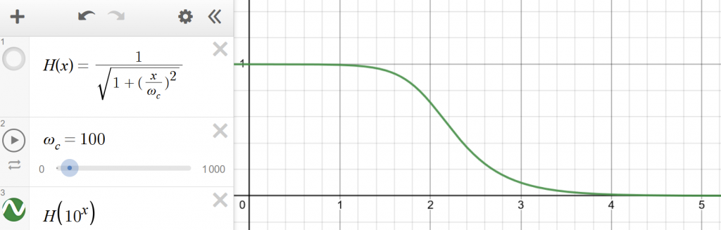
We have mentioned that loudness and amplitude in audio are also logarithmically related. Therefore, replacing the vertical axis with a logarithmic scale as well.

It is clear that the response declines after the cutoff frequency $\omega_c$. The speed of decline approaches -10dB/dec (-20dB/dec for loudness, which is about -6dB/octave).
So far, we have filtered the signals above the cutoff frequency using a circuit. Now it’s just a matter of implementing it on the computer!
The ratio of the frequency domain of the input and output signals is also the ratio of their Fourier transforms. Extending the Fourier transform from the imaginary axis to the whole complex plane, we can get the Laplace transform.
The ratio of the Laplace transform of the input to the output signal is called the transfer function. It is the network function of the circuit. Usually, we let $s=j\omega$. There for the transfer function will be:
$H(s)=\frac{Y}{X}=\frac{1}{1+s\tau}$
Digital filter
Audio samples are discrete. Applying z-transform to the transfer function, we should get:
$Y_n=Y_{n-1}+\frac{T_c}{\tau}(X_{n-1}-Y_{n-1})$
$T_c$ is the sampling period. Let $a=\frac {T}{\tau}=T\omega_c$, which is also known as the filter coefficient, the basic formula of first-order low-pass digital filter will be:
$Y_n=aY_{n-1}+(1-a)Y_{n-1}$
It is incrediblly simple, isn’t it. All we need to do is iterating the samples using a loop:
double f_c=500; //Cutoff frequency
double sampleRate=44100.0; //Sample rate
double a=f_c/sampleRate; //Filter coefficient
for(int i=1;i<samples.length();i++){
    samples[i]=a*samples[i]+(1.0-a)*samples[i-1];//JUST ITERATE IT!
}
//Done.
That’s right, the time complexity of this filter is O(n), and no trigonometric operations involved!
In addition to first-order filters, multiple filters can be connected in series to achieve a more rapid drop in signal after the cutoff frequency.
There are also some filters that use different transfer functions. For example, Butterworth filters, Chebyshev filters, elliptic filters, etc. They may have some interesting properties. For example, the Butterworth filter can create a drive at the cutoff frequency by varying the $Q$ value.

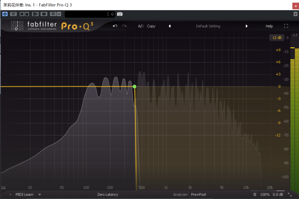
If you use EQ plugins a lot, you’ll probably find this curve looks familiar. Let’s see what’s in the software:

Remember the above -6dB/octave rate of decay? Let’s verify that.

…here it is.